Bridge & Gantry Heavy Duty Machining

Ultra-rigid, Powerful, Long-lasting

For the largest, heaviest 3 to 5 axis parts look no further than a Jupiter bridge or gantry mill. The bridge and gantry lines come in a wide array of sizes and each mill is custom built to your unique application needs. 3 axis, 5 face, and full 5 axis simultaneous configurations are all available. Want to install a massive rotary on the table for long cylindrical parts? We can do that too!

Customer-driven Configuration Flexibility

Jupiter partners with the world’s leading CNC system providers to deliver whatever platform you prefer.

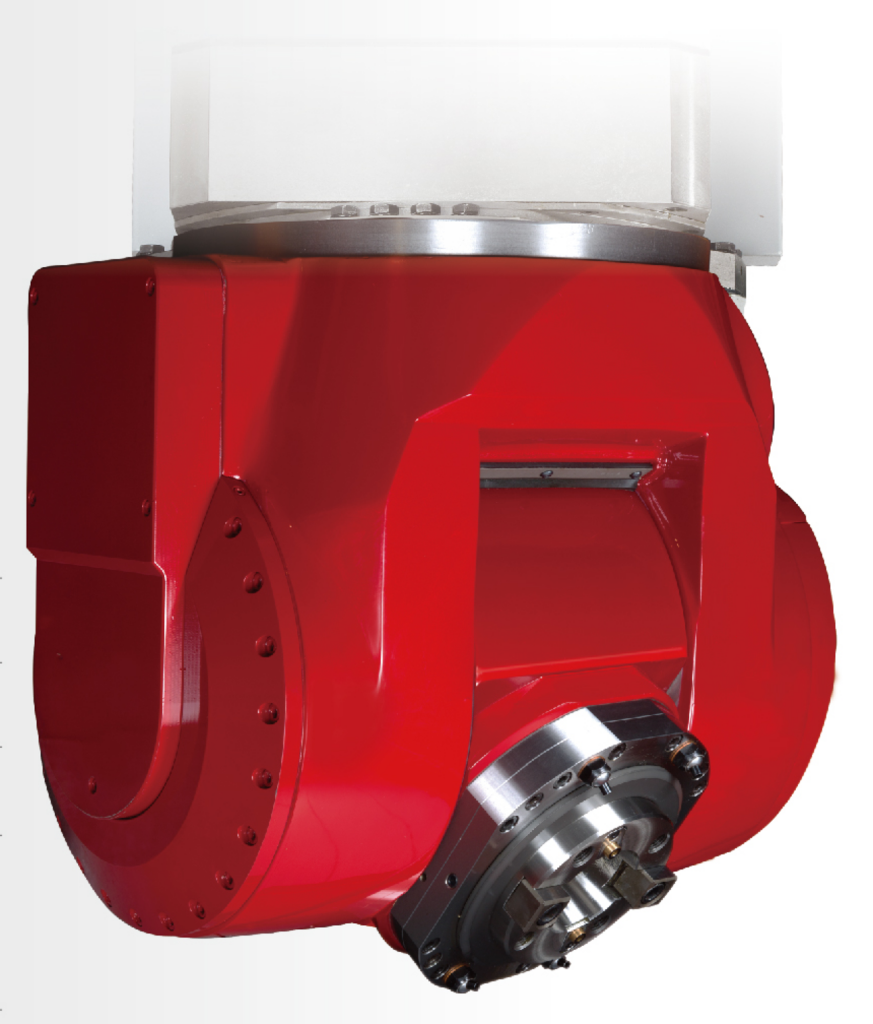
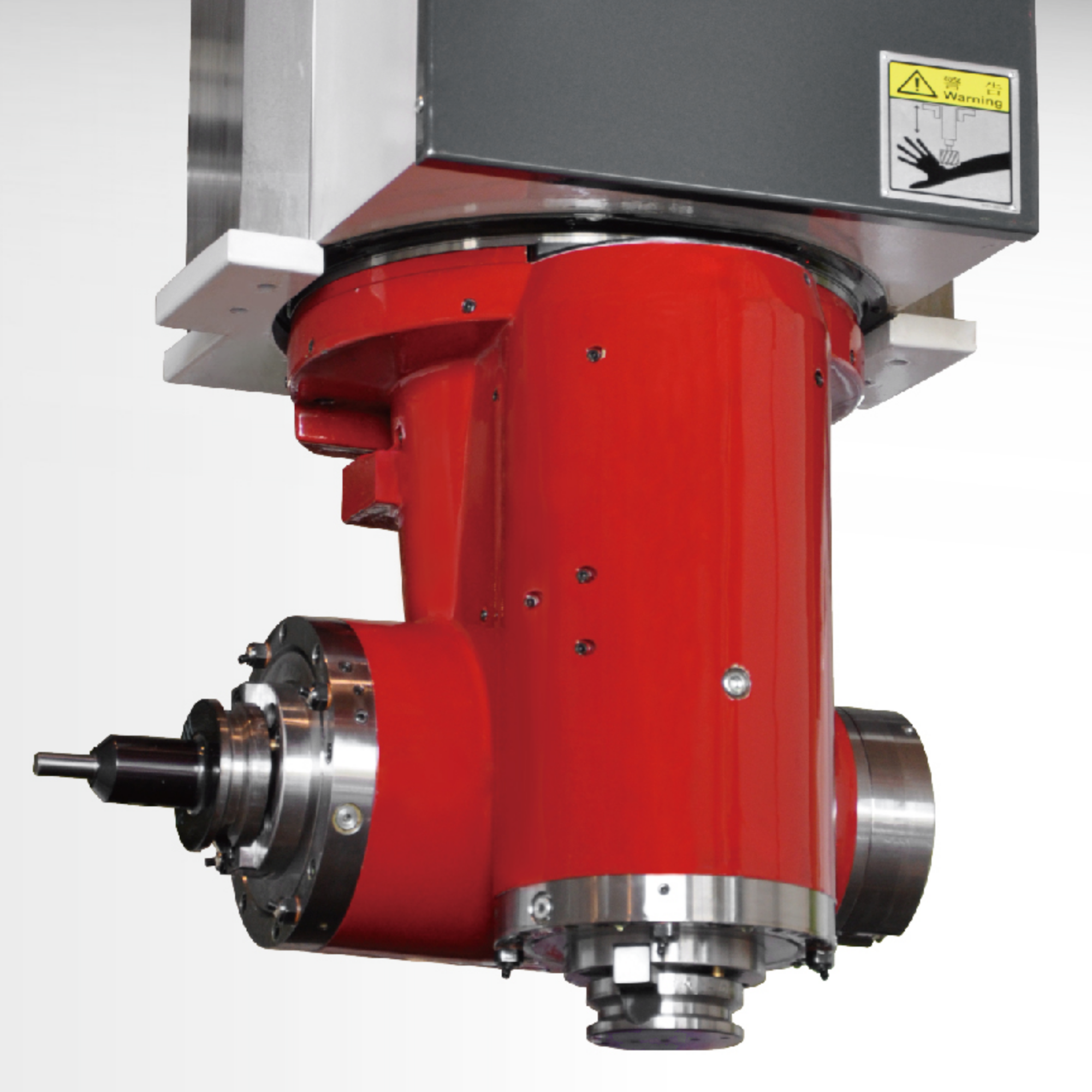
High Performance Spindles

All Jupiter spindles feature Japanese bearings and come in dual-contact / Big Plus taper as part of their standard configuration. Each spindle is hand-built by master craftsmen before being precision balanced and run-in for over 72 hours. Direct drive and belt-driven styles are available depending on your application needs.

Premium Ballscrews & Linear Guides

All Jupiter machines come with C1-class premium super accurate ballscrews and roller linear guides manufactured by motion industry leaders for the most demanding applications.

Incredible Accuracy

All Jupiter machine tools are laser pitch error compensated and ball bar inspected both before leaving the factory and at time of installation on the customer’s floor. You deserve micron precision.

Faultless Reliability

Jupiter components are always chosen with long-term reliability in mind, so that you don’t need to keep reliability in your mind. New Jupiter machines come standard with a two year manufacturer’s warranty… but you won’t need it!

Jupiter Bridge & Gantry Mills

For the Very Largest Applications

Product Gallery

Specifications, Standard Features, & Options

Monster 4th axis rotary? Yes, we can!

Jupiter bridge and gantry mills support a wide range of tapers, RPMs, and horsepower combinations. 3 axis, 5 face, and full 5 axis simultaneous heads are available for all platforms. For parts demanding the highest precision and repeatability, select our JBM series of high performance bridge mills. For the heaviest, largest, and longest parts design your ideal work envelope with our JGM gantry series.

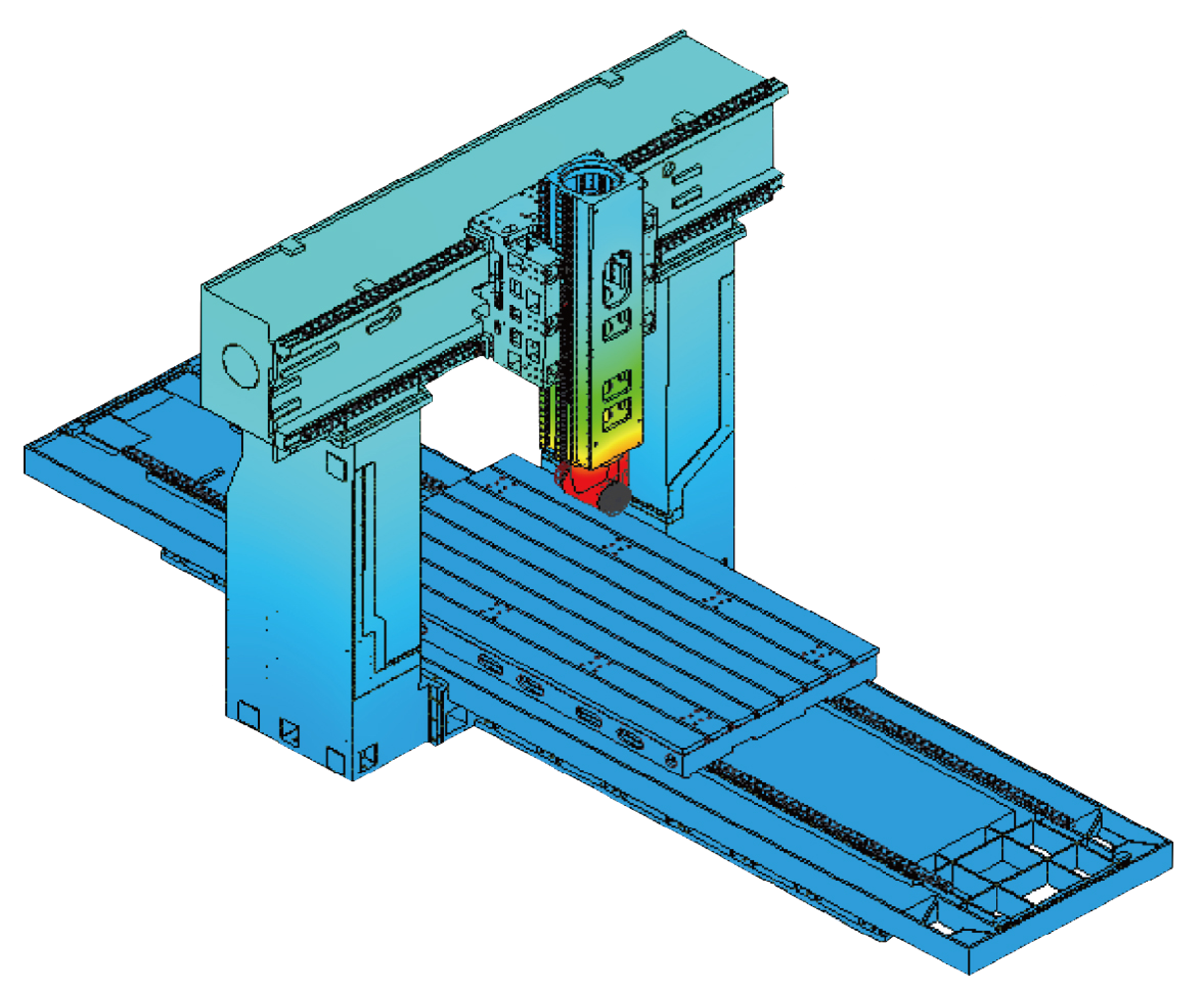
All Jupiter casting designs undergo exhaustive Finite Element Analysis to optimize performance under real-world loading conditions.

SPECIFICATIONS UNIT BRIDGE MIN BRIDGE MAX
CNC SYSTEM Control Fanuc 31i Fanuc 31i
Configuration 15″ Touchpanel 15″ Touchpanel
Motors & Amps Alpha Class Alpha Class
TRAVEL X Axis in 86.61 244.09
Y Axis in 59.06 118.11
Z Axis in 29.92 39.37
Spindle Nose to Table Min in 4.53 4.92
Spindle Nose to Table Max in 35.04 46.26
Distance Between Columns in 59.06 118.11
MOTION Way Type – X Axis Roller Guide Roller Guide
Way Type – Y Axis Roller Guide Roller Guide
Way Type – Z Axis Hardened Box Way Hardened Box Way
Rapid Traverse – X Axis ipm 787 472
Rapid Traverse – Y Axis ipm 787 591
Rapid Traverse – Z Axis ipm 591 394
TABLE Length (X Axis) in 78.74 236.22
Width (Y Axis) in 47.24 98.43
Max Load lb 8,800 55,000
SPINDLE Configuration Multiple styles based on application need
ATC Capacity Tools 40 40
Max Tool Weight lb 44 44
Max Tool Dia. – Adj. Occupied in 4.92 4.92
Max Tool Dia. – Adj. Empty in 8.46 8.46
Max Tool Length in 13.78 15.75
DIMENSIONS Machine Weight lb 28,600 125,400
Length (X Axis) in 246 591
Width (Y Axis) in 175 235
Height in 157 207
SPECIFICATIONS UNIT GANTRY MIN GANTRY MAX
CNC SYSTEM Control Fanuc 31i Fanuc 31i
Configuration 15″ Touchpanel 15″ Touchpanel
Motors & Amps Alpha Class Alpha Class
TRAVEL X Axis mm 2,200 6,200
Y Axis mm 1,500 3,000
Z Axis mm 760 1,000
Spindle Nose to Table Min mm 115 125
Spindle Nose to Table Max mm 890 1,175
Distance Between Columns mm 1,500 3,000
MOTION Way Type – X Axis Roller Guide Roller Guide
Way Type – Y Axis Roller Guide Roller Guide
Way Type – Z Axis Hardened Box Way Hardened Box Way
Rapid Traverse – X Axis m/min 20 12
Rapid Traverse – Y Axis m/min 20 15
Rapid Traverse – Z Axis m/min 15 10
TABLE Length (X Axis) mm 2,000 6,000
Width (Y Axis) mm 1,200 2,500
Max Load kg 4,000 25,000
SPINDLE Configuration Multiple styles based on application need
ATC Capacity Tools 40 40
Max Tool Weight kg 20 20
Max Tool Dia. – Adj. Occupied mm 125 125
Max Tool Dia. – Adj. Empty mm 215 215
Max Tool Length mm 400 400
DIMENSIONS Machine Weight kg 13,000 57,000
Length (X Axis) mm 6,230 15,000
Width (Y Axis) mm 4,430 5,950
Height mm 4,000 5,250
SPECIFICATIONS UNIT GANTRY MIN GANTRY MAX
CNC SYSTEM Control Fanuc 31i Fanuc 31i
Configuration 15″ Touchpanel 15″ Touchpanel
Motors & Amps Alpha Class Alpha Class
TRAVEL X Axis in 125.98 322.83
Y Axis in 106.30 165.35
Z Axis in 39.37 39.37
Spindle Nose to Table Min in 7.87 7.87
Spindle Nose to Table Max in 47.24 47.24
Distance Between Columns in 78.74 137.80
MOTION Way Type – X Axis Roller Guide Roller Guide
Way Type – Y Axis Roller Guide Roller Guide
Way Type – Z Axis Hardened Box Way Hardened Box Way
Rapid Traverse – X Axis ipm 519 394
Rapid Traverse – Y Axis ipm 591 472
Rapid Traverse – Z Axis ipm 394 394
TABLE Length (X Axis) in 118.11 314.96
Width (Y Axis) in 62.99 118.11
Max Load lb 22,000 77,000
SPINDLE Configuration Multiple styles based on application need
ATC Capacity Tools 60 60
Max Tool Weight lb 44 44
Max Tool Dia. – Adj. Occupied in 4.92 4.92
Max Tool Dia. – Adj. Empty in 8.46 8.46
Max Tool Length in 15.75 15.75
DIMENSIONS Machine Weight lb 66,000 171,600
Length (X Axis) in 327 788
Width (Y Axis) in 233 296
Height in 213 221
SPECIFICATIONS UNIT GANTRY MIN GANTRY MAX
CNC SYSTEM Control Fanuc 31i Fanuc 31i
Configuration 15″ Touchpanel 15″ Touchpanel
Motors & Amps Alpha Class Alpha Class
TRAVEL X Axis mm 3,200 8,200
Y Axis mm 2,700 4,200
Z Axis mm 1,000 1,000
Spindle Nose to Table Min mm 200 200
Spindle Nose to Table Max mm 1,200 1,200
Distance Between Columns mm 2,000 3,500
MOTION Way Type – X Axis Roller Guide Roller Guide
Way Type – Y Axis Roller Guide Roller Guide
Way Type – Z Axis Hardened Box Way Hardened Box Way
Rapid Traverse – X Axis m/min 15 10
Rapid Traverse – Y Axis m/min 15 12
Rapid Traverse – Z Axis m/min 10 10
TABLE Length (X Axis) mm 3,000 8,000
Width (Y Axis) mm 1,600 3,000
Max Load kg 10,000 35,000
SPINDLE Configuration Multiple styles based on application need
ATC Capacity Tools 60 60
Max Tool Weight kg 20 20
Max Tool Dia. – Adj. Occupied mm 125 125
Max Tool Dia. – Adj. Empty mm 215 215
Max Tool Length mm 400 400
DIMENSIONS Machine Weight kg 30,000 78,000
Length (X Axis) mm 8,300 20,000
Width (Y Axis) mm 5,900 7,500
Height mm 5,400 5,600
  • 4th Axis Rotary
  • Air gun
  • Automatic lubrication
  • Automatic power-off
  • Automatic Tool Changer
  • Chip conveyor, chain type
  • Chip conveyor, dual spirals along X-axis
  • Chip conveyor, magnetic
  • Coolant system
  • Coolant thru spindle w/ filter and tank @ 300 PSI or 1000 PSI
  • Enclosed splash guard
  • Fanuc 31i-MB5 Plus with 15” LCD Touchscreen
  • Fanuc Data Server (2 GB)
  • Foot switch for tool clamping and unclamping
  • Heidenhain optical scales on X, Y, & Z  axes
  • Heidenhain rotary encoders for A & C axes
  • Leveling bolts and pads
  • Oil skimmer
  • Remote MPG
  • Rigid tapping
  • RS-232, USB, and CAT-5 interfaces
  • Spindle air blast
  • Spindle oil cooler
  • Spindle – CAT-40 DC, CAT-50 DC, HSK-A63, HSK-A100
  • Toolbox & adjustment tools
  • Transformer
  • Work air blast
  • Work lamp

Machine specifications published for reference only and are subject to change without notice. Not all features available on all models. Always see your local Jupiter representative for up-to-date information.